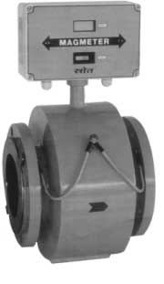
MAGMETER
ELECTROMAGNETIC FLOW METER |


|
| INTRODUCTION
: |
The electromagnetic flow meter virtually approaches the ideal
flow meter suitable for wide range of liquid flow measurements
even with very low conductivities. The meter offers no resistance
to flow hence the pressure drop is almost negligible. The
measurement being based on Faraday’s law of Electromagnetic
induction, is independent of viscosity, density, pressure
& temperature of flowing medium. The measurement is not
affected by solid impurities as long as the min. conductivity
of 5 s/cm is available. It is a true volumetric flow measurement.
We offer various materials of construction for meter lining
& electrodes to cover majority of corrosive liquids.
The Technique called as ‘pulsed DC’ is used which
offers very high zero stability & accuracy of measurement.
The standard current output of 4-20 mA DC is provided which
is linearly proportional to volumetric flow rate & additional
frequency output is also provided.
|
| MAGENETIC
FLOW METER : |
The method of flow measurement based on Faraday’s
law of electromagnetic induction. When a conductor
moves within a magnetic field, voltage is induced
in it which is proportional to the velocity of conductor.
in this case the conductor is flowing media .the equation
is as below
.
E=B.v.d.
Where ,
E = Induced voltage [proportional to velocity]
B = Magnetic flux density
v = mean vcity of the media
d = Distance between the sensing electrodes
For a given size of flow tube & compatible am
plifier the flux density ‘B’
is constant the distance the electrodes is constant.
Hence, the induced
voltage is proportional to the velocity of the flowing
media .Thus the unit
can be calibrated in terms of volumetric flow rate
by knowing the cross
-sectional area of the tube |
|
| PRINCIPAL
ADVANTAGES : |
| 1. |
Use of pulsed DC magnetisation &
auto zero technique offers excellent long term zero
stability |
| 2. |
Measurement is independent of velocity
profile across the diameter of the pipe-line. |
| 3. |
Measurement result are independent of
density , viscosity, pressure temperature , soli-impurities&
conductivity variation[above5 siemens] |
| 4. |
No additional pressure drop across the
meter which relieves the process designer while sizing
his pumping requirement. Simple to install as no special
precautions of straight pipe lengths required |
| 5. |
Compatible with virtually all corrosive/
non- corrosive liquids . |
| 6. |
Protection class offered IP65. |
| 7. |
higher ratio of return on investment
to investment. |
| 8. |
Bath-tub curve remains flatter for very
long period |
|
| APPLICATIONS
: |
| This meter is more suitable
with those fluids which present difficulties in handling.
Fluids such as effluents, slurries pulps, brine and
other highly corrosive liquids, acids and bases, fermenter
wash, molasses etc. Following industries can find lot
of application of this flow measurement technique. |
| |
| Following industries
can find lot of application of this flow measurement
technique. |
 |
Effluent treatment plants |
 |
Water supply schemes |
 |
Steel & Aluminium |
 |
Chemical/Pharmaceutical |
 |
Food & Drugs |
 |
Sewage treatment plants |
 |
Sugar industries & Distilleries |
 |
Pulp & paper |
 |
Petrochemicals /fertilizers |
 |
Petrochemicals & Fertilizers. |
|
|
| SPECIFICATIONS
: |
| METERING TUBE : SROAT 1000 |
| Meter size : |
DN 10 to DN 350 for higher size consult facory |
| Media Pressure : |
up to DN-100 to DN 200- Pn16 DN-250 to DN 350-PN
10 |
| Media temperature : |
PTEF Liners 0-150 c max. For other Liners 0-90
c max. |
| Ambient Temperature Range: |
0-50 c |
| Flanges Standard : |
ANSI / DIN /BS SMS/ Triclamp |
| Power Supply to filed coils : |
Plused DC |
Materials :
|
pipe :
Electrode :
Liner :
Flanges :
Coil Housing : |
ss 316 [non magnetic
ss 316 / Hastelloy C/Pt /Ta /Ti.
PTFE / Neoprene / soft Rubber /Hard Rubber.
carbon steel / ss 316 / ss 316 L /ss 304.
Carbon steel / ss, Epoxy Painted. |
|
| TRANSMITTER
SROAT 1000 A : |
| Type : |
Integral mounted [standard] Remote
Mounted [on request] |
| Min. Media Conductivity : |
5 s / cm [ for lower conductivities
consult factory] |
| Signal Output : |
4-20 mA dc isolated in max. 600
ohms.
Additional option : Pulsed output with adjustable count rate
from 1 count / hr to 10 counts / Hr.[open collector with 100
mA / 24 dc capacity] |
Singal output (cont.) Or
Frequency output : |
0-10 Khz prop.To 0-100% flow rate
[open colloctor with 10 mA/24 v dc max.] |
| Coil Excitation Frequency : |
Selectble by links
a) 25Hz
b)12.5Hz
c)6.25Hz
d)3.15Hz |
| Local Display : |
a)31/2 digit LCD calibrated in %
engineering units
b) 8 digit LCD non resettable type for totalized quantity. |
| Flow Velocity Range : |
0.1 m/s to 10 m/s |
| Accuracy : |
+ 0.5% of reading [at ref. Conditions
]between 100%to 10% of calibrated range +0.75% of reading
for flow rate between 10% to 5% [refer accuracy graf] |
| Ref. conditions : |
Power supply nominal. temperature 27 c+2 c |
| Repeatability : |
+0.2% of reading |
| Ambient temperature Drift : |
0 50 c |
| Temperature drift : |
+0.015% per c max. |
| Material of Housing : |
Al. Die cast / ss 304 . |
| Power supply : |
230 v ac/110v ac 50 Hz/24vdc. |
| Damping : |
Adjustable from 5 to 30 secs. |
| Cable Entries : |
4 no. For remote amplier. 2 no.
For integral amplier. ½ NPT/ 1/2 BSP/ pg4 [female]
for Al. Die cast Housing 3/4 ET for ss 304 Housing |
| Ingress Protection : |
IP-65 |
|
| FLOW
RATE TABLE : Flow
Rate At V= 1m/s |
| DN |
M3 / Hr |
Lpm |
LPS |
| 10 |
0.282 |
4.712 |
0.078 |
| 15 |
0.636 |
10.602 |
0.176 |
| 20 |
1.130 |
18.849 |
0.314 |
| 25 |
1.767 |
29.452 |
0.490 |
| 32 |
2.895 |
48.254 |
0.804 |
| 40 |
4.523 |
75.398 |
1.256 |
| 50 |
7.068 |
117.809 |
1.963 |
| 65 |
11.945 |
199.098 |
3.318 |
| 80 |
18.095 |
301.592 |
5.026 |
| 100 |
28.274 |
471.238 |
7.853 |
| 125 |
44.178 |
736.310 |
12.271 |
| 150 |
63.617 |
1060.287 |
17.671 |
| 200 |
113.097 |
1884.955 |
31.415 |
| 250 |
176.714 |
2945.243 |
49.087 |
| 300 |
254.469 |
4241.150 |
70.685 |
|
|
| ORDERING
INFORMATION : |
| Flow Meter Size |
Order Code MS 03 |
| MS 01 |
DN 10 |
| MS 02 |
DN 15 |
| MS 03 |
DN 20 |
| MS 04 |
DN 25 |
| MS 05 |
DN 32 |
| MS 06 |
DN 40 |
| MS 07 |
DN 50 |
| MS 08 |
DN 65 |
| MS 09 |
DN 80 |
| MS 10 |
DN 100 |
| MS 11 |
DN 125 |
| MS 12 |
DN 150 |
| MS 13 |
DN 200 |
| MS 14 |
DN 250 |
| MS 15 |
DN 300 |
| MS 16 |
Any Other |
|
| Flange / End Connection Standards |
Order Code
FS 07 |
| FS 01 |
DIN Pn40 |
| FS 02 |
DIN PN 16 |
| FS 03 |
DINPN 10 |
| FS 04 |
ANSI 300 |
| FS 05 |
ANSI 150 |
| FS 06 |
SMS |
| FS 07 |
Tri-clamp |
| FS 08 |
Any other |
| Liner Material |
Order Code LM 02 |
| LM 01 |
Teflon[PTFE] |
| LM 02 |
Neoprene |
| LM 03 |
Soft Rubber |
| LM 04 |
Hard Rubber |
| LM 05 |
Any other |
|
| Electrode Material |
Order Code EM 04 |
| EM 01 |
Stainless steel 316 |
| EM 02 |
Hastelloy C |
| EM 03 |
Tantalum |
| EM 04 |
Titanium |
| EM 05 |
Platinum |
| EM 06 |
Any other |
|
| Flange / End Connection Material |
Order Code FM 03 |
| FS 01 |
Carbon steel |
| FS 02 |
Stainless steel 304 |
| FS 03 |
Stainless steel 316 |
| FS 04 |
Stainless steel 3161 |
|
| Power Supply |
Order Code 01 |
| 01 |
110 + 10%V AC, 50 Hz |
| 02 |
230 + 10%v AC ,50 Hz |
| 03 |
24 Vdc+10% |
|
| Flow Transmitter |
Order Code FT 02 |
| FT 01 |
Integral [ AL. Diecast] |
| FT 02 |
Remote [ AL. Diecast] |
|
|
Download .pdf
|